| Fenian Ram Interior Photos / 03TorpedoCompressedAirCylinder&Piston Joseph Costa, Paterson Museum Curator of Photography 5/19/2006 |
03BraytonOilEngineCylinderNPiston.jpg
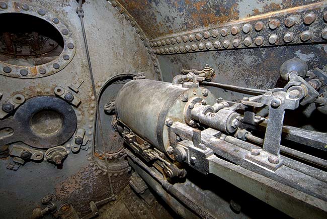
After reading an account on the web stating that the engine had been removed to power a forge I thought this must be the air compressor cylinders. After conferring with Gary McCue and looking at a diagram of a Brayton Oil EngineI discovered this IS the engine. It is fired and operates at very low pressures compared to today's internal combustion engines. This is one of 2 cylinders, the other being on the same side towards the rear of the crew's compartment. During the test runs of the sub the hull was pressurized to the same pressure as the surrounding water and the engine drew air from the crew's compartment. Holland planned to add a dedicated compressed air supply for the engine but the Fenians stole the sub before he was able to complete it.
The verticle pushrod and bellcrank assembly just to left of center is the linkage that allows the commander to open and close the Kingston valves for flooding and blowing the ballast tanks. If you look closely at the photos of the rear of the compartment you will see it's mate just behind the differential gear to right of center.
Notice the riveted construction of the iron plates comprising the hull. The rivets would have been heated to a cherry red in a forge, then placed in each hole where a worker on one side hammered the small end to mushroom it over while a worker on the other side bucked the rivet head with a heavy iron bucking bar. Between the sound and heat in that enclosed space it must have been a miserable job.
Many thanks to Gary McCue for helping keep my descriptions accurate.